News
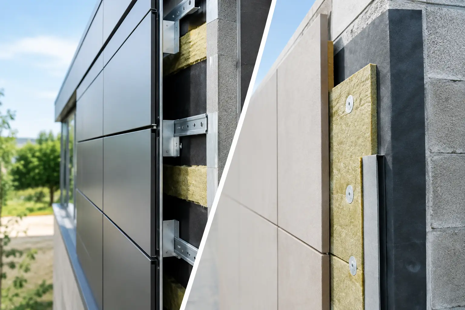
A facade can look flawless at turnover and still carry a hidden moisture problem behind the cladding. The decisive question is not whether the exterior panels shed rain – they should. It is whether the full wall assembly can manage water that reaches its outer layers. That is the central distinction in rainscreen versus barrier walls, and it affects detailing, material selection, testing, maintenance planning, and long-term building value.
For high-rise, hospitality, airport, commercial, and institutional work, the choice cannot be reduced to a visual preference or a panel profile. It must respond to climate exposure, building geometry, substrate conditions, window interfaces, code requirements, expected service life, and the performance of the tested assembly. Architects and contractors need to evaluate the drainage plane, air barrier, insulation, cavity, attachment system, and exterior cladding as a coordinated envelope.
What Defines a Barrier Wall?
A barrier wall is intended to stop water at its exterior face. Its performance depends on highly continuous exterior materials, sealed joints, durable coatings, and carefully maintained transitions at penetrations, openings, corners, and terminations. In principle, rainwater should not move beyond the outside surface.
This approach can be appropriate in limited conditions. Monolithic precast concrete, fully adhered waterproofing assemblies, and certain masonry wall designs can perform as barrier systems when their joints and interfaces are designed for the expected movement and exposure. The requirement is exacting: the exterior plane must remain continuous despite thermal movement, structural deflection, sealant aging, construction tolerances, and routine building maintenance.
The risk is concentrated at the details. A failed sealant joint, imperfect flashing transition, or unanticipated movement path can allow water behind the exterior finish. If there is no drained cavity or clear exit path, moisture may remain in the assembly longer than intended. That can contribute to staining, corrosion, freeze-thaw distress, mold risk, insulation degradation, or deterioration of adjacent materials, depending on the wall construction.
Barrier walls are therefore not automatically unsuitable. They demand a realistic assessment of workmanship, exposure, access for inspection, and the consequences of small discontinuities. On complex facades with many openings, deep reveals, multiple material changes, and high wind-driven rain exposure, relying on a perfectly sealed exterior face can create a narrow margin for error.
Rainscreen Versus Barrier Walls: The Functional Difference
A rainscreen wall accepts a practical fact of exterior construction: some water may pass the outer cladding plane. Rather than treating that possibility as a failure, the system provides a controlled drainage and drying zone behind the cladding. The exterior panels act as the first line of defense, reducing the volume and force of rain reaching the backup wall. A ventilated cavity, drainage plane, flashings, and weeps then direct incidental moisture outward.
The water-resistive barrier and air barrier are typically located behind the cavity, where they form the critical weather-control plane. Exterior insulation may be placed outboard of the backup wall, depending on the specified system and thermal strategy. Cladding attachments hold the panels away from the wall, preserving the cavity required for drainage and, in many assemblies, ventilation.
The distinction is not simply “sealed” versus “open.” Proper rainscreen facades still require sealed and detailed transitions. Joints, panel returns, perimeter closures, window interfaces, flashings, and penetrations must be engineered to manage water and air. The difference is redundancy. A rainscreen design does not assume that the visible cladding will remain the sole moisture-control layer for the life of the building.
Pressure moderation can also be part of the design. Where compartmentalized rainscreen principles are used, cavity baffles and vent locations help reduce pressure differences that could otherwise drive water inward. The exact approach depends on panel geometry, joint design, cavity depth, wind loads, and the tested facade system. It should never be assumed from a generic detail.
Why the Cavity Matters
The cavity behind a rainscreen panel is a working part of the building envelope, not unused space. It provides a route for water to drain downward and exit through flashing or weep details. When designed for ventilation, it can also support drying by allowing air movement behind the cladding.
A cavity must remain continuous enough to perform. Mortar droppings, insulation displacement, poorly located clips, improperly installed closures, or incompatible accessory details can restrict drainage. At horizontal interruptions, shelf angles, floor lines, window heads, and transitions between cladding types, the design must provide positive flashing and a clear path to the exterior.
The cavity also changes how the facade handles dimensional movement. Aluminum composite material, solid aluminum panels, and other metal cladding products expand and contract with temperature changes. A properly engineered attachment system allows the panels and subframing to move as intended while protecting the drainage plane behind them. Rigidly restraining components that are designed to float can transfer stress to joints, fasteners, and panel edges.
Selecting Cladding for a Drained and Ventilated Assembly
Panel selection should begin with the complete assembly, not color, finish, or nominal thickness alone. Metal composite and aluminum panel systems can deliver crisp geometry, large-format coverage, durable finishes, and broad design freedom. Their performance as facade cladding, however, depends on the engineered relationship between the panel, rout-and-return fabrication or cassette design, subframing, fasteners, cavity, insulation, membrane, and backup wall.
For specification teams, several issues deserve early coordination:
- The attachment system must accommodate design wind pressures, building movement, panel movement, and substrate tolerances.
- The wall membrane must be compatible with adjacent materials and detailed continuously at windows, parapets, penetrations, and transitions.
- Flashings, end dams, drip edges, and weeps must direct water outward without blocking the cavity.
- Fire performance must be evaluated at the wall-assembly level, including insulation, air cavity conditions, cladding, attachment components, and perimeter details.
Fire-rated cladding is particularly relevant on larger and taller buildings, where facade decisions carry heightened life-safety and code implications. A panel classification alone does not establish compliance for a specific exterior wall. Project teams should evaluate applicable code provisions and the relevant assembly evidence, including NFPA 285 in the United States, CAN/ULC-S134 in Canada, BS 8414, or EN 13501 where those standards apply. The authority having jurisdiction, project code consultant, and facade engineer determine what evidence is required for the building and assembly under review.
Alubond supports specification-driven facades with fire-rated panel options, metal skins, custom finishes, and manufacturing control across core materials, coatings, and bonding technologies. That breadth gives project teams greater freedom to align facade expression with the tested-system requirements and procurement demands of major construction programs.
When a Barrier Strategy May Still Be Appropriate
There are projects where a barrier approach remains reasonable. A low-rise building in a dry climate with simple geometry, limited openings, protected elevations, and accessible joints may have a manageable risk profile. Certain fully bonded or monolithic exterior systems are also designed around continuous water exclusion rather than a drained cavity.
Even then, the design team should ask difficult questions. How will sealants be inspected and renewed? Where will movement occur? What happens when water enters at a window perimeter or roof-wall transition? Can the system dry toward the exterior or interior? Is the exterior surface exposed to wind-driven rain, salt spray, thermal cycling, or frequent wash-down conditions?
A barrier wall becomes less forgiving as facade complexity increases. Tall towers, coastal sites, podium transitions, curtain wall interfaces, curved volumes, and mixed-material elevations all introduce more joints and more opportunities for water to bypass the outer face. In those cases, a drained and ventilated rainscreen strategy often provides a more durable path because it plans for water management beyond the first surface.
Detail the Interfaces, Not Just the Field Panels
Large panel elevations receive attention because they define the architecture. Failures, however, commonly begin at interfaces: window perimeters, parapets, base conditions, balconies, expansion joints, signage supports, louvers, and transitions to glazing or masonry. These areas require clear responsibility across trades and coordinated shop drawings before fabrication begins.
Mockups are valuable because they reveal whether the intended drainage paths, joint widths, fastener locations, closure components, and flashing sequences can actually be built. For demanding projects, performance testing of representative wall sections can validate resistance to water penetration, air leakage, structural loading, and movement before full installation proceeds. Field quality control should confirm that the as-built assembly matches the approved details, particularly where membranes and flashings will later be concealed.
The strongest facade strategy is not the one that assumes perfect conditions. It is the one that makes water predictable, gives it a route out, accommodates movement, and supports the fire and code obligations of the complete wall. When the building is expected to perform for decades, that discipline is where architectural ambition becomes lasting envelope performance.
RECENT POSTS

September 28 , 2026

September 26 , 2026

September 24 , 2026

September 22 , 2026

September 20 , 2026

September 18 , 2026

September 16 , 2026

September 14 , 2026

September 12 , 2026

September 10 , 2026

September 8 , 2026

September 6 , 2026

September 4 , 2026

September 2 , 2026

August 31 , 2026

August 29 , 2026

August 27 , 2026

August 25 , 2026

August 23 , 2026

August 21 , 2026

August 19 , 2026

August 17 , 2026

August 15 , 2026

August 13 , 2026

August 12 , 2026

August 12 , 2026

August 12 , 2026

August 12 , 2026

August 12 , 2026

August 12 , 2026

August 12 , 2026

August 12 , 2026

November 2 , 2022

April 26 , 2022

