News
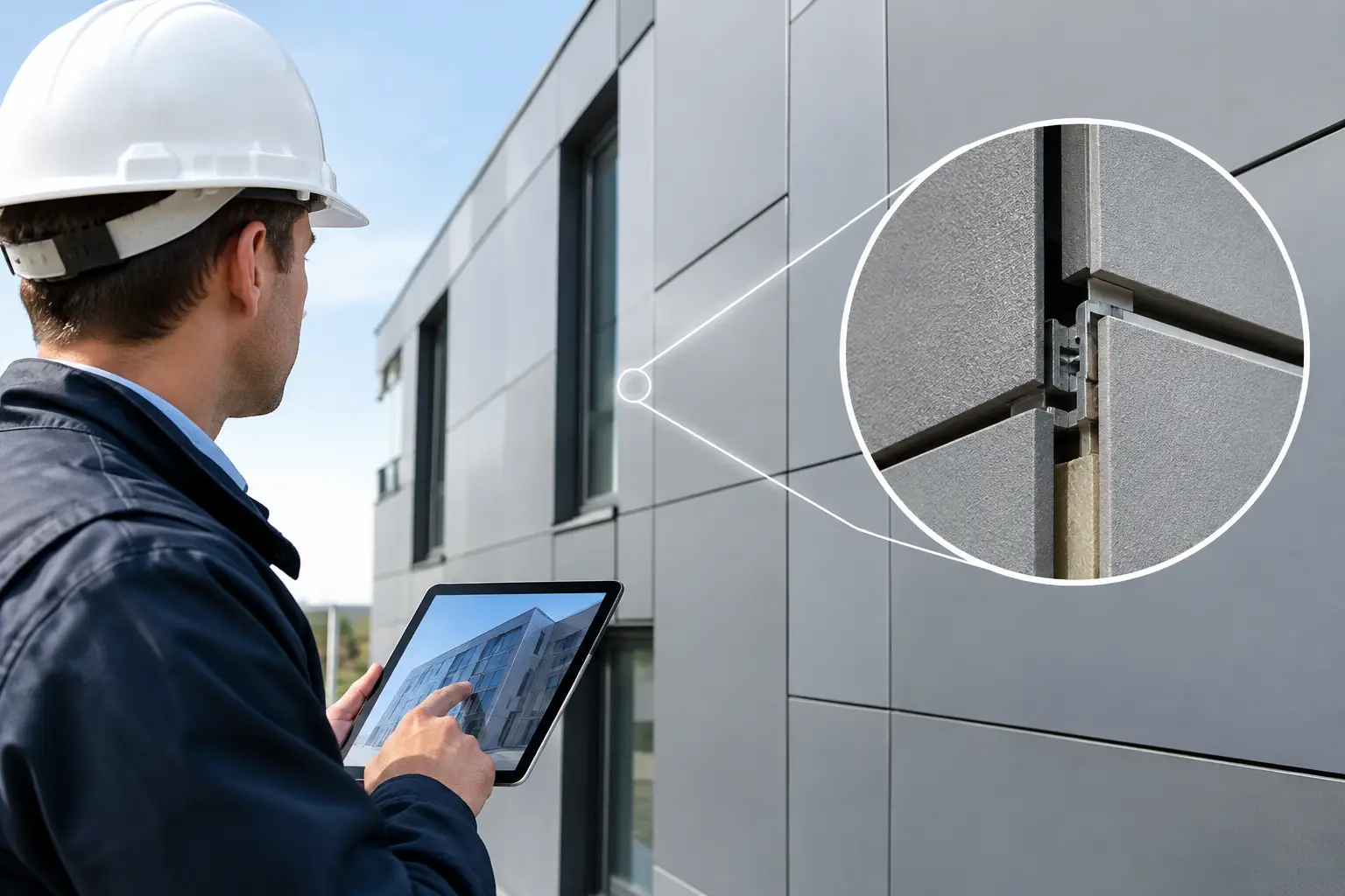
A 20-foot facade panel does not experience the same temperature as the air reported at a nearby weather station. Dark finishes can heat substantially in direct sun, while nighttime radiation, wind exposure, insulation levels, and the wall cavity all influence the panel’s actual temperature. That is why knowing how to calculate thermal movement is a design requirement, not a shop-drawing afterthought.
For aluminum composite material, solid aluminum, and other metal facade systems, thermal expansion must be accommodated through the complete assembly: panels, joints, fasteners, rails, brackets, perimeter interfaces, and transitions to glazing or other cladding. A panel can be correctly fabricated and still perform poorly if its restraint points and joint capacity do not match anticipated movement.
The Thermal Movement Formula
Linear thermal movement is calculated with a simple equation:
ΔL = α × L × ΔT
Where ΔL is the change in length, α is the coefficient of thermal expansion for the material, L is the original panel or component length, and ΔT is the expected temperature change.
In US customary units, the coefficient must be expressed per degree Fahrenheit and the temperature range in degrees Fahrenheit. In metric calculations, use a coefficient per degree Celsius with dimensions in millimeters or meters. The units must remain consistent throughout the calculation.
For aluminum, a commonly used coefficient of thermal expansion is approximately 12.8 × 10⁻⁶ inches per inch per °F, or 23 × 10⁻⁶ meters per meter per °C. This value is useful for preliminary design, but final calculations should use the declared coefficient for the specific panel, alloy, skin thickness, support system, and fabrication method. Composite panels should not be assigned a generic value without checking the manufacturer’s technical data, because material construction and tested system details matter.
How to Calculate Thermal Movement Step by Step
Begin by identifying the component that is free to move. This may be the full panel length, a cassette return, an aluminum rail, a steel support member, or a continuous trim. Do not assume that every component in a facade moves together. Differential expansion between dissimilar materials is often the more demanding condition.
Next, establish the design temperature range. This is not simply the difference between the average January and July temperatures. A facade engineer should consider the lowest credible installation or service temperature and the highest credible material temperature in service. Solar absorption is a major variable. A dark, south- or west-facing metal surface can run far warmer than ambient air, while a light-colored or highly reflective finish may have a lower peak surface temperature.
Then apply the formula. Consider an aluminum-faced panel that is 240 inches long, or 20 feet. Assume a conservative service temperature change of 140°F, from -20°F to 120°F.
ΔL = 12.8 × 10⁻⁶ × 240 × 140
The result is 0.430 inches, or approximately 7/16 inch of movement over the panel length.
That movement is not theoretical. If both ends are rigidly fixed, the panel or its attachment system must absorb the resulting stress. Possible outcomes include oil canning, bowed panels, enlarged fastener holes, distorted joints, failed sealant adhesion, or noise caused by movement against adjacent components. In a pressure-equalized rainscreen, those conditions can also compromise drainage paths and the intended behavior of the wall assembly.
Calculate From the Fixed Point
The location of the fixed point changes how the movement is distributed. If the 20-foot panel in the example is fixed at one end and allowed to slide at the other, nearly the full 7/16 inch must be available in the direction of the sliding end.
If the panel is fixed at its center, movement is divided in two directions. Each end may move approximately 7/32 inch relative to the center, assuming uniform temperature and symmetric support. This approach can reduce demands at an individual perimeter condition, but it requires disciplined coordination of clips, slots, reveals, and adjoining materials.
The relevant question is never only, “How much will this panel grow?” It is also, “Where is that growth directed, and what detail permits it?”
Temperature Range Is a Project-Specific Decision
The correct ΔT depends on climate, elevation, orientation, panel color, solar exposure, and the project’s performance criteria. An airport facade in a high-desert climate faces a different thermal profile than a shaded urban podium in a humid coastal market. High-rise elevations can also experience more severe wind cooling and exposure than protected lower levels.
Finish selection deserves particular attention. Deep black, charcoal, and saturated colors support strong architectural expression, but they may reach higher surface temperatures than white, silver, or other reflective finishes. This does not rule out dark finishes. It means the thermal assumptions, movement joints, and fixing strategy must be engineered for the actual exposure.
The same discipline applies to fire-rated facade panels. A fire classification or successful wall-assembly test, including NFPA 285, EN 13501, BS 8414, or CAN/ULC-S134 where applicable, addresses a defined fire-performance requirement. It does not eliminate the need to accommodate everyday thermal movement. Fire safety, weather resistance, structural capacity, and movement control must be evaluated as coordinated parts of the specified facade system.
Designing Joints and Fixings for Movement
A joint should provide more than visual separation. It must supply sufficient dimensional capacity after accounting for fabrication tolerances, installation tolerances, building drift, substrate movement, and expected thermal expansion. If a reveal is visually narrow, its usable movement capacity may be far less than its face dimension once panel edges, gaskets, baffles, and tolerances are considered.
Fixings are equally critical. Most panel systems rely on a defined fixed point to establish panel position and sliding points to permit expansion and contraction. At sliding points, fastener slots, clip geometry, washer dimensions, and tightening procedures must work together. An oversized hole alone is not a complete movement detail if the fastener head or washer clamps the panel so tightly that sliding cannot occur.
Avoid field modifications that undermine this design intent. Added fasteners, sealant placed within a designed drainage or movement zone, or rigid attachments to adjacent trims can unintentionally restrain a panel. Fabricators and installers should follow the approved system details rather than treating movement provisions as optional tolerances.
Differential Movement Often Governs the Detail
Facade assemblies combine materials with different coefficients of expansion. Aluminum panels may be attached to aluminum extrusions, galvanized steel rails, stainless steel anchors, concrete structure, masonry backup, or steel framing. Each responds differently to a temperature change, and the support structure may also move due to creep, shrinkage, live-load deflection, or interstory drift.
For example, aluminum expands roughly twice as much as carbon steel over the same length and temperature range. A 20-foot aluminum panel mounted to a steel rail can therefore develop relative movement even when both materials see identical temperatures. The attachment must permit that relative movement without transferring unintended stress into the panel face or the weather barrier.
Panel dimensions are only one part of the calculation. Long continuous trims, parapet caps, soffit components, sunshade blades, and rail sections can create greater cumulative movement because of their length. Treat each continuous element as its own calculation and locate expansion breaks accordingly.
Practical Checks Before Releasing Fabrication
Before fabrication begins, the project team should verify the panel’s maximum unsupported dimension, intended fixed-point location, required sliding capacity, joint width at minimum and maximum temperatures, and compatibility with the chosen subframe. Confirm that shop drawings identify slot orientation and that installation instructions define where fasteners are fixed versus sliding.
It is also prudent to review panel movement against adjacent glazing, doors, louvers, sealant joints, and corner conditions. A detail that works in a flat field elevation can fail at a return, coping, or transition where multiple directions of movement converge.
For large-scale architectural envelopes, thermal movement should be resolved early, while panel module, finish selection, and support layout are still flexible. The strongest facade details do not fight material movement. They give it a controlled path, preserve the design intent, and protect the long-term performance expected from a high-value building envelope.
RECENT POSTS

November 5 , 2026

November 3 , 2026

November 1 , 2026

October 30 , 2026

October 28 , 2026

October 26 , 2026

October 24 , 2026

October 22 , 2026

October 20 , 2026

October 18 , 2026

October 16 , 2026

October 14 , 2026

October 12 , 2026

October 10 , 2026

October 8 , 2026

October 6 , 2026

October 4 , 2026

October 2 , 2026

September 30 , 2026

September 28 , 2026

September 26 , 2026

September 24 , 2026

September 22 , 2026

September 20 , 2026

September 18 , 2026

September 16 , 2026

September 14 , 2026

September 12 , 2026

September 10 , 2026

September 8 , 2026

September 6 , 2026

September 4 , 2026

September 2 , 2026

August 31 , 2026

August 29 , 2026

August 27 , 2026

August 25 , 2026

August 23 , 2026

August 21 , 2026

August 19 , 2026

August 17 , 2026

August 15 , 2026

August 13 , 2026

August 12 , 2026

August 12 , 2026

August 12 , 2026

August 12 , 2026

August 12 , 2026

August 12 , 2026

August 12 , 2026

August 12 , 2026

November 2 , 2022

April 26 , 2022

