News
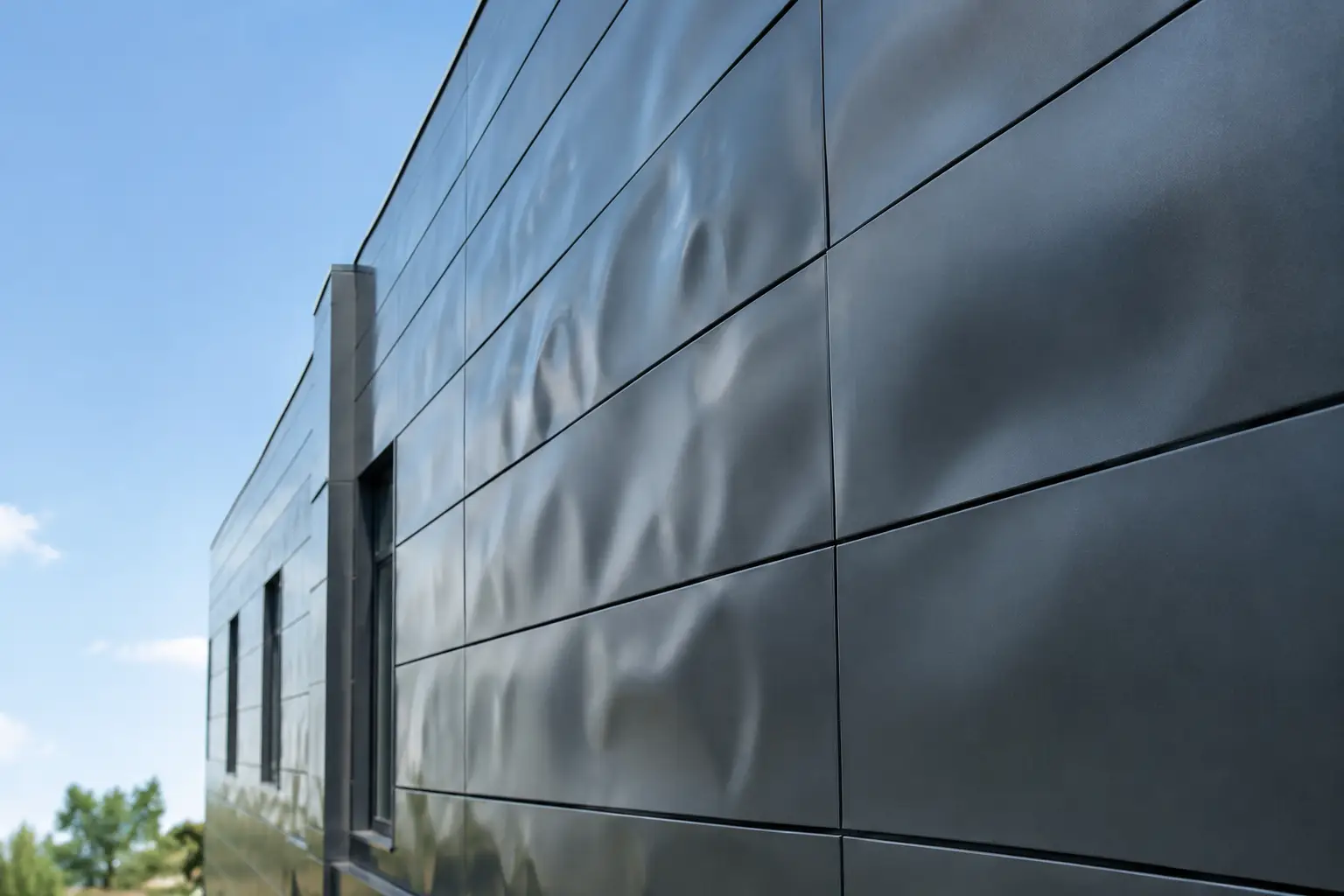
A facade can meet its structural, weather-resistance, and fire-performance requirements yet still draw immediate scrutiny when broad metal surfaces appear wavy under changing daylight. For project teams asking what causes facade oil canning, the answer is rarely one isolated defect. It is usually the visible result of material stress, panel geometry, fabrication practice, installation restraint, and the unforgiving optics of a reflective finish.
Oil canning is especially relevant on large-format aluminum, steel, stainless steel, copper, and metal composite facade panels. It must be assessed early because the appearance of flatness is shaped as much by design and viewing conditions as by the panel itself.
What Is Facade Oil Canning?
Oil canning is a visible, localized waviness or slight buckling in a thin metal face. The surface may appear flat from one viewing angle and show shallow ripples from another. On a sunny elevation, reflected light can make minor movement appear far more pronounced than it does under diffuse skies.
The term does not automatically mean that a panel has failed, that the wall is leaking, or that its fire classification has changed. In many cases, it is an aesthetic condition within the normal behavior of thin-gauge architectural metal. However, pronounced or inconsistent distortion can also indicate an underlying issue in fabrication, attachment, substrate alignment, or thermal movement management. That distinction requires a disciplined facade review rather than a judgment based on photographs alone.
The Main Causes of Facade Oil Canning
Residual Stress in the Metal Skin
Metal coil is produced, leveled, slit, coated, transported, and formed before it becomes a facade panel. Each step can introduce or release residual stress. When a thin sheet contains uneven internal stress, the metal may move slightly as it is cut, bonded, routed, bent, or exposed to temperature changes.
This is not unique to one alloy or manufacturer. Aluminum is lightweight and highly formable, while steel, stainless steel, copper, bronze, and titanium have their own stiffness, expansion, forming, and surface characteristics. The selected skin thickness, temper, coil flatness, and finish all influence how readily a panel reveals waviness.
For composite material, the bond between the metal skins and core contributes significant stiffness. Even so, the outer metal face remains a thin architectural surface, and visual perfection across large reflective planes should never be assumed without considering panel dimensions, support conditions, and finish selection.
Thermal Expansion and Differential Movement
Exterior metal moves as its temperature changes. Dark colors, south- and west-facing elevations, high solar exposure, and insulated wall assemblies can create substantial surface-temperature variation during a single day. Aluminum expands more than many adjacent materials, so a panel restrained too tightly at multiple points may develop stress as it attempts to move.
The concern is not thermal movement alone. It is differential movement between the cladding panel, rails, anchors, framing, and backup wall. If the attachment strategy does not provide calculated allowance for expansion and contraction, small stresses may become visible as oil canning, edge read-through, bowed panels, or distorted joints.
A properly engineered facade system identifies fixed and sliding points, joint widths, rail movement, and directional expansion before fabrication begins. These details should be coordinated with actual panel lengths, not treated as generic installation notes.
Panel Size, Aspect Ratio, and Unsupported Area
Large panels create strong architectural impact, but they also increase visual risk. As panel width and height increase, the unsupported field becomes more susceptible to visible movement. Very wide, shallow panels and very tall, narrow panels can respond differently, depending on the support layout and direction of metal grain.
Panel returns, cassette depth, stiffeners, intermediate supports, and perimeter engagement all affect apparent flatness. A panel with deep formed edges and properly designed support can perform differently from a flat sheet with minimal reinforcement, even if both use the same face metal.
There is a practical trade-off. More stiffeners or closer support spacing may improve visual control, but they add fabrication complexity, cost, and potential read-through if they are improperly bonded or positioned. The appropriate solution depends on panel module, finish, exposure, system geometry, and project appearance criteria.
Fabrication-Induced Stress
Routing, folding, brake forming, punching, drilling, adhesive application, stiffener placement, and protective-film removal can all affect a panel’s final appearance. Excessive forming pressure, inconsistent return dimensions, overworked corners, or nonuniform adhesive cure can introduce localized stress.
Fabricators must also account for directional characteristics in coated coil and metal skins. Maintaining consistent orientation across an elevation helps control visual variation, particularly with metallic, brushed, directional, or high-gloss finishes. Mixing panel orientation can make normal surface variation appear to be a flatness problem.
Stiffeners require particular care. They should support the panel without creating hard points that telegraph through the face. Bonding methods, adhesive bead size, cure conditions, spacing, and thermal compatibility should follow the panel-system requirements and approved fabrication procedures.
Substrate Irregularity and Installation Restraint
A high-quality panel cannot correct a wall that is out of plane. If rails, brackets, shims, or backup framing vary beyond the system’s tolerances, the cladding may be pulled into that irregular geometry. The resulting distortion can appear as broad waves, corner stress, joint misalignment, or localized dimpling near fasteners.
Over-tightened fasteners are another common cause. A fastener that clamps a panel where movement should occur can create visible stress around the fixing point. Likewise, forcing a panel into position to close an inconsistent joint can transfer installation error directly into the finished surface.
Field verification matters. Before panels are installed across an elevation, installers should confirm rail alignment, bracket adjustment, panel dimensions, engagement depth, joint consistency, and the designated fixed-versus-moving attachment points. Mockups are especially valuable for reflective or large-format cladding because they reveal visual effects that shop drawings cannot fully predict.
Wind Pressure, Building Movement, and Service Loads
Facade panels are designed to resist project-specific wind loads, but pressure and suction can make surface movement more visible, particularly on thin or large panels. High-rise corners, parapets, airport canopies, open parking structures, and coastal projects may experience demanding localized pressures.
Building drift, slab-edge movement, and deflection of supporting members also affect facade behavior. A panel system should accommodate these conditions without transferring excessive stress to the metal face. The relevant analysis is system-wide: panel, attachment, rails, brackets, anchors, backup wall, and movement joints must work together.
Finish, Color, and Viewing Conditions
Not every perceived oil canning issue is a fabrication or installation defect. Finish selection can amplify ordinary surface variation. Glossy coatings, metallic colors, mirror-like stainless steel, polished copper, and smooth dark panels reflect light sharply. Low-angle sun, nearby glazing, water, landscaping, and moving vehicles may make shallow waviness appear dramatic.
Matte finishes, textured coatings, lighter colors, perforation, reveals, and smaller panel modules can reduce visual sensitivity. These are design choices, not afterthoughts. Where exceptional visual uniformity is required, specifications should identify the intended viewing distance, lighting conditions, panel orientation, and acceptance criteria before procurement.
How to Reduce Oil Canning Risk in Specifications
The strongest approach begins during design development. Specify the panel material, face-metal thickness, finish, panel dimensions, support strategy, joint design, and movement provisions as coordinated parts of one facade system. Avoid relying on a generic flatness statement when the design includes expansive high-gloss panels or demanding sightlines.
A representative full-scale mockup should be reviewed under morning, midday, and late-afternoon light. It should include actual panel sizes, corners, returns, stiffeners, joints, rails, and attachment components. Reviewing a small sample indoors will not reproduce the visual behavior of a completed elevation.
For fire-rated assemblies, maintain the tested and approved wall-system configuration. Changes made solely to address appearance, such as altered panel thickness, new stiffener arrangements, different insulation, or revised attachment spacing, should be evaluated for their impact on the specified system and applicable code requirements. Fire performance and visual quality must be coordinated, not treated as separate decisions.
Alubond supports this level of coordination through broad metal composite and fire-rated cladding options, custom finishes, and a global manufacturing platform built for specification-driven projects. The right panel selection is only one part of the result. Fabrication discipline and installation control complete the facade.
Evaluating an Existing Facade
When oil canning is reported after installation, begin with objective observation. Record panel location, orientation, time of day, weather, viewing distance, and whether the appearance changes with light or temperature. Compare affected panels with adjacent units made from the same material and installed under similar conditions.
Then inspect panel dimensions, rail alignment, joint widths, support locations, fastener conditions, and signs of forced installation. If the waviness is localized near a stiffener, fastener, corner, or substrate transition, the investigation should focus there. If it occurs broadly across a reflective elevation and varies by sunlight, the condition may be primarily optical, though the system should still be checked against approved tolerances.
The best facades do not leave visual quality to chance. They match material behavior, panel geometry, tested system requirements, fabrication controls, and installation tolerances to the architectural ambition of the building.
RECENT POSTS

October 28 , 2026

October 26 , 2026

October 24 , 2026

October 22 , 2026

October 20 , 2026

October 18 , 2026

October 16 , 2026

October 14 , 2026

October 12 , 2026

October 10 , 2026

October 8 , 2026

October 6 , 2026

October 4 , 2026

October 2 , 2026

September 30 , 2026

September 28 , 2026

September 26 , 2026

September 24 , 2026

September 22 , 2026

September 20 , 2026

September 18 , 2026

September 16 , 2026

September 14 , 2026

September 12 , 2026

September 10 , 2026

September 8 , 2026

September 6 , 2026

September 4 , 2026

September 2 , 2026

August 31 , 2026

August 29 , 2026

August 27 , 2026

August 25 , 2026

August 23 , 2026

August 21 , 2026

August 19 , 2026

August 17 , 2026

August 15 , 2026

August 13 , 2026

August 12 , 2026

August 12 , 2026

August 12 , 2026

August 12 , 2026

August 12 , 2026

August 12 , 2026

August 12 , 2026

August 12 , 2026

November 2 , 2022

April 26 , 2022

