News
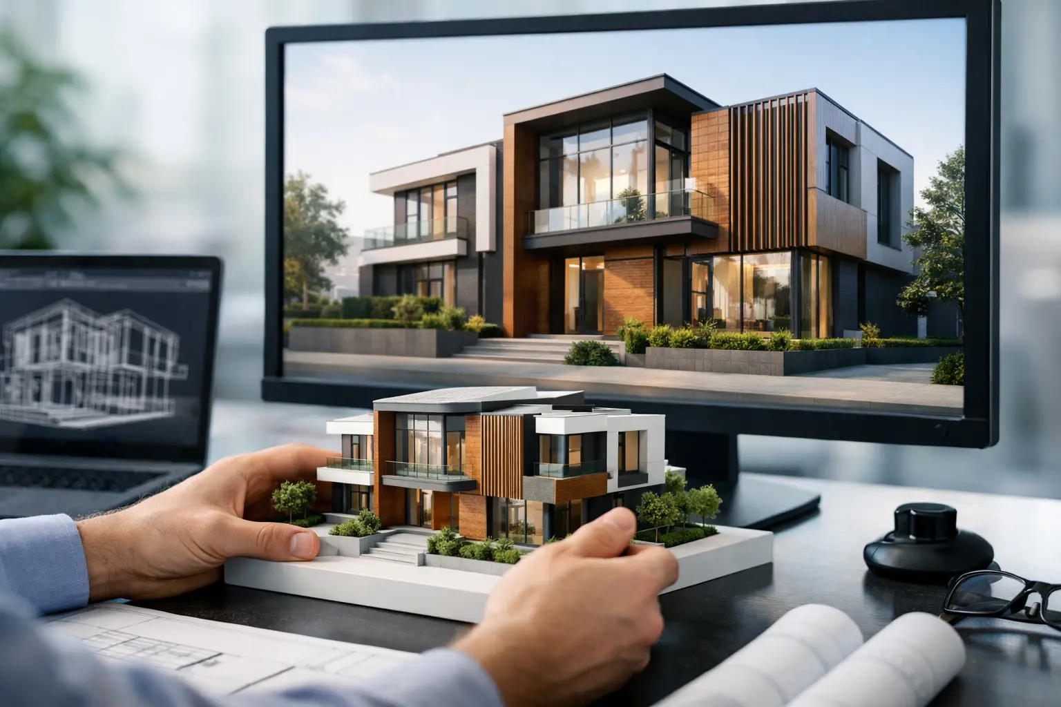
A facade can look resolved in elevation and still create expensive questions at the shop-drawing stage: Where does the corner return terminate? Does a metallic finish shift across folded panels? Can the proposed cassette depth accommodate insulation, rails, and movement joints? 3D facade design visualization brings these questions forward, when design changes are faster, less disruptive, and more economical.
For towers, airports, hospitality developments, corporate campuses, and large commercial buildings, visualization is not simply a presentation exercise. It is a coordination instrument for the building envelope. It allows architects, facade consultants, fabricators, contractors, and owners to evaluate the visible architectural intent alongside the physical logic required to build it.
What 3D Facade Design Visualization Should Deliver
A useful facade model does more than apply a color to a massing model. It should communicate panel module, joint rhythm, orientation, folded geometry, feature zones, transitions, openings, parapets, soffits, and material boundaries. The objective is to establish a shared, reviewable representation of what the facade is intended to become.
That matters because composite panel systems are defined by relationships. A 4 mm aluminum composite panel, a solid aluminum panel, and an exotic metal skin may achieve very different visual effects, but each must work within a panelization strategy, support system, fabrication method, and approved wall assembly. The model helps the project team see these relationships before they become field conditions.
At its best, 3D visualization connects three decisions that are often made separately: architectural expression, material selection, and construction sequencing. A design team may choose a deep reveal for shadow and scale, for example, while the fabricator assesses whether that reveal can be consistently formed and installed. The facade consultant can then review drainage, movement, interfaces, and continuity of the specified assembly.
Start With Panel Logic, Not Surface Rendering
Highly polished renderings can make an early concept persuasive, but they can also conceal unresolved fabrication issues. The more valuable workflow begins with panel logic: establish the module, identify fixed dimensions, locate movement joints, and define how panels turn at corners and openings. Only then should the team focus on photorealistic finish studies.
A panel grid should respond to the building rather than fight it. Structural bays, floor lines, window mullions, slab edges, access requirements, and expected panel sizes all influence the final rhythm. On a high-rise, a grid that appears disciplined from 500 feet away may produce narrow infill strips at every floor or misaligned joints around window bands. In a 3D model, these conflicts are visible early.
The same discipline applies to signature elements. Curved volumes, faceted entrances, fins, crowns, canopies, and media-feature facades deserve their own panelization study. A smooth digital surface does not automatically translate into practical flat-panel geometry. Depending on radius, module, and material, the intended curve may require faceting, roll forming, routed-and-returned panels, or a different cladding approach altogether.
Model Interfaces as Carefully as Feature Walls
Most installation risk occurs at interfaces, not across broad uninterrupted elevations. Model the junction between cladding and glazing, roof membranes, louvers, doors, precast, stone, curtain wall, and grade conditions. These areas determine whether the facade reads as one coherent composition and whether field teams have sufficient room to complete the work.
The model does not replace detailed drawings or engineering. It makes the questions more precise. Instead of asking whether a corner is feasible, the team can review a specific corner condition, its panel sequence, and its relationship to adjacent systems.
Evaluate Color, Finish, and Light Under Real Conditions
Finish selection is one of the strongest reasons to use a 3D model, particularly for large elevations. A digital study can compare solid colors, metallics, brushed effects, woodgrain, stone-inspired finishes, custom-painted surfaces, and metal skins in the same architectural context. It allows stakeholders to assess whether an accent color has sufficient presence, whether a dark facade needs relief, or whether a pattern becomes visually busy across an entire building.
However, rendering is an approximation, not a finish approval. Screen settings, rendering engines, image compression, orientation, and light conditions all influence perceived color. Metallic and directional finishes require particular care because panel orientation and reflected light can create variation that is entirely expected in the finished facade.
The practical approach is to use visualization to narrow choices, then validate the selected finish with physical samples and, where project scale warrants it, a representative mock-up. This sequence protects design intent without asking a digital image to do work that belongs to actual material review.
For global projects, that distinction is especially important. The visual character of a facade in direct Gulf sunlight can differ significantly from the same finish under an overcast North American sky. Climate, surrounding buildings, viewing distance, and facade orientation should influence the review process.
Use Visualization to Coordinate Fire-Rated Facade Systems
A facade model can identify where fire-rated requirements and design ambitions intersect. It can map material zones, show transitions between panel types, and help teams understand where details change around openings, podiums, spandrels, and vertical breaks. This is useful when a project includes FR-A1, FR-A2, FR-B1, or FR-B2 materials, solid aluminum panels, and other exterior finishes within one envelope strategy.
But visual coordination is not evidence of code compliance. A model cannot certify an assembly, establish a required rating, or substitute for tested system documentation. Compliance depends on the applicable code, authority having jurisdiction, the complete wall assembly, insulation, air and water barrier, attachment system, cavity conditions, and the specific products being used.
For projects subject to NFPA 285, EN 13501, BS 8414, CAN/ULC-S134, or comparable requirements, the design team should use the model alongside manufacturer technical data, test reports, engineering review, and project-specific submittals. The benefit is clarity: the model makes it easier to confirm that the visually proposed material locations align with the documented system approach.
A Better Review Process for Every Stakeholder
3D facade design visualization becomes most effective when every stakeholder reviews the model through the lens of their responsibility. Architects should test proportion, hierarchy, color balance, and how the facade supports the overall building identity. Facade consultants should focus on envelope transitions, drainage paths, movement, and continuity. Fabricators should examine routability, returns, panel sizes, tolerances, and installation sequence.
Contractors and procurement teams need a different view. They need to understand where custom shapes, special finishes, long-lead materials, or complex access requirements could affect schedule and cost. Owners need confidence that the approved concept can be delivered at the expected quality level, not merely presented convincingly at design review.
This is where a model should be used iteratively. Early-stage studies may be simple and fast, intended to compare massing, panel direction, and finish families. As the project advances, the model should gain meaningful detail at high-risk areas. Not every fastener needs to be modeled during concept design, but every visually or technically critical transition should be identified before fabrication begins.
Questions Worth Asking in a Model Review
A productive review is specific. Ask whether panel joints align with glazing lines and major building datums. Ask where panel sizes change and whether those changes are intentional. Ask whether corners, returns, and soffits preserve the desired finish direction. Ask whether the selected material is appropriate for exposure, geometry, and performance requirements.
Also ask what the model does not show. Concealed support systems, waterproofing continuity, tolerances, site conditions, and tested assembly requirements need separate technical confirmation. Recognizing this boundary keeps visualization credible and useful.
From Digital Intent to Fabrication Confidence
The strongest facade programs use digital visualization as the front end of a disciplined delivery process. The model establishes intent. Material samples confirm finish. Technical documentation defines performance. Shop drawings resolve fabrication and interfaces. Mock-ups demonstrate workmanship and final appearance. Each stage reduces uncertainty for the next.
Alubond supports this process with a broad range of fire-rated composite panels, solid aluminum panels, custom finishes, and specialty metal skins produced through an integrated global manufacturing platform. For specification-driven projects, material availability and documented performance must be considered as early as visual expression.
The most effective next step is not another generic rendering. It is a focused model review of the facade areas that carry the greatest architectural, technical, and procurement risk. Resolve those conditions while changes are still digital, and the finished building has a far better chance of matching the design team’s original intent.
RECENT POSTS

September 26 , 2026

September 24 , 2026

September 22 , 2026

September 20 , 2026

September 18 , 2026

September 16 , 2026

September 14 , 2026

September 12 , 2026

September 10 , 2026

September 8 , 2026

September 6 , 2026

September 4 , 2026

September 2 , 2026

August 31 , 2026

August 29 , 2026

August 27 , 2026

August 25 , 2026

August 23 , 2026

August 21 , 2026

August 19 , 2026

August 17 , 2026

August 15 , 2026

August 13 , 2026

August 12 , 2026

August 12 , 2026

August 12 , 2026

August 12 , 2026

August 12 , 2026

August 12 , 2026

August 12 , 2026

August 12 , 2026

November 2 , 2022

April 26 , 2022

